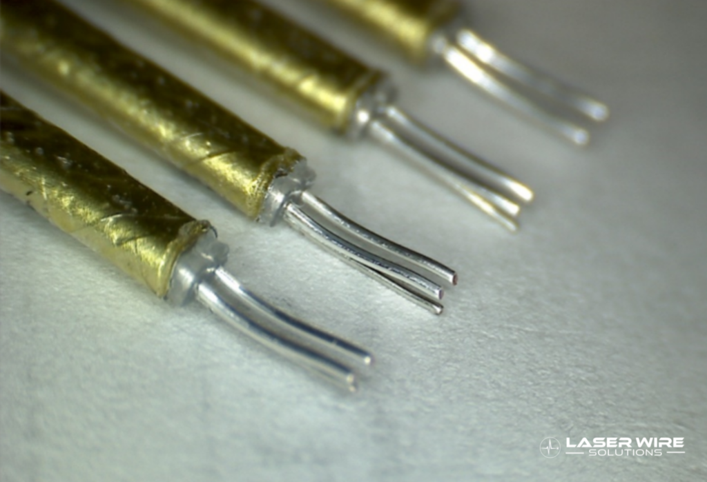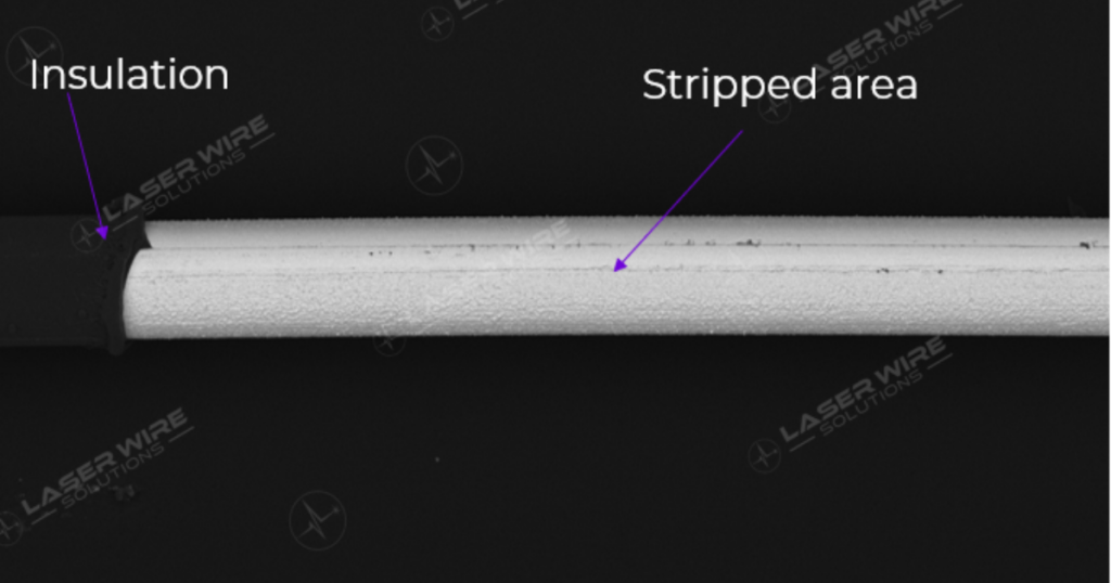
Medical wire stripping acceptance criteria should describe the required strip geometry, permissible conductor condition, allowable insulation residue and inspection methods needed for the component’s next manufacturing step. Define these requirements before process development so that the supplier, manufacturing team and quality team evaluate the same result.
“Clean strip” or “no damage” can express the design intent, but those phrases need an agreed interpretation. An inspectable specification explains what to examine, how to measure it and what decision follows. The goal is a controlled component requirement that supports the finished device’s performance.
Start with the downstream function
Ask what the exposed conductor must do next. A wire intended for welding may need different surface and geometry controls from one prepared for crimping, soldering or bonding.
Identify which strip features influence that operation and which features affect the device in service. These become candidates for critical-to-quality characteristics, subject to the manufacturer’s design and risk review.
For example, an insulation window used to create an electrical connection needs a defined position relative to the assembly. Its appearance alone cannot show that it is correctly located. Conversely, a dimensional pass does not establish that the exposed surface is suitable for the joining process.
Translate both concerns into the specification rather than expecting final inspection to discover the intended requirements.
Which geometric features should be controlled?
Strip length and position
Define the exposed length, its tolerance and the datum used for measurement. For a window strip, specify its location as well as its length. Explain whether the requirement applies around the full circumference or to a defined processed area.
Include the condition in which the part is measured. A flexible wire can be presented differently under tension, in a fixture or free on a bench. Choose a measurement method appropriate to the feature and use it consistently.
Insulation edge and adjacent material
Describe the acceptable edge condition and any limit on material disturbance beyond the intended strip zone. Where retained insulation is functionally important, consider how inspection will detect damage to it.
Avoid adding arbitrary numeric limits because they appear precise. Limits should come from design needs and demonstrated measurement capability, then be approved through the applicable quality process.
Conductor condition
State the relevant conductor concerns, such as notching, broken strands, deformation or changes to a required surface layer. Define how suspect conditions will be assessed and escalated.
For plated wire, determine whether the plating is functionally important and how its condition will be evaluated. A surface that appears bright under one lighting arrangement may still require a different inspection method to answer the engineering question.
How should residue be specified?
First define what residue means for the component: remaining insulation, loose particles or another observed surface condition. Then link the acceptance requirement to the downstream need.
Choose an inspection method with enough sensitivity to detect the condition of interest. Optical inspection may be suitable for some features; a development investigation may require additional analysis. Do not prescribe SEM for every production part simply because it produces detailed images.
Where useful, build a reference set of acceptable, borderline and rejected samples. Record the inspection conditions so the reference remains meaningful. Photographs without magnification, scale or lighting information can create disagreement rather than resolve it.
A statement such as “no visible residue” is incomplete unless “visible” refers to an agreed method and the method is suitable for the intended requirement.
What belongs in the inspection plan?
For each controlled characteristic, record the drawing reference, acceptance limit, inspection method, equipment, sampling approach and required record. Assign responsibility for release and for handling results outside the limits.
As a practical example, a strip-length requirement should identify the measurement datum and method. A conductor-condition requirement should identify the inspection conditions and defect definitions. A downstream joint-strength requirement should reference the approved joining and test method rather than being assumed from strip appearance.
Define sampling through the manufacturer’s quality and risk processes. There is no single inspection frequency appropriate to every wire, device or production stage. Development samples, qualification builds and routine supply may need different plans.
Check that measurement variation is small enough to support the acceptance decision. A tight drawing tolerance offers little control if the inspection method cannot reliably distinguish passing and failing parts.
How does this relate to validation and QMSR?
Inspection criteria and process validation answer related but different questions. Acceptance criteria define the required output. Validation addresses whether a process can consistently achieve its specified result under the relevant conditions.
The FDA’s QMSR became effective on February 2, 2026 and incorporates ISO 13485:2016 by reference. References written solely around the previous wording of 21 CFR 820.75 therefore need review before reuse in current website copy.
The GHTF process validation guidance remains useful background for planning process specifications and qualification work. Apply it alongside current applicable requirements and your quality system. A programmable laser recipe, an equipment qualification or an ISO certificate does not by itself establish that a particular component process is validated.
What should you agree before supplier transfer?
Send the supplier the approved drawing revision, material specification and relevant acceptance plan. Agree which records accompany supplied lots and which changes require notification or approval.
During development, review actual samples together and resolve ambiguous defect definitions. Keep the approved reference images and inspection instructions under appropriate document control.
For ongoing supply, establish a response to nonconforming material and a route for reviewing material, fixture or process changes. LWS offers medical component processing and inspection support, with the scope agreed for the application. Define that scope before assuming a standard documentation package covers every requirement.
Frequently asked questions
Can we specify “no conductor damage”?
Yes, as an intent, but define the relevant defect types and how they will be detected. The acceptance decision should be reproducible using the agreed inspection method.
Does every stripped medical wire need SEM inspection?
No. Select inspection methods based on the feature, required detection capability and quality plan. Development analysis and routine production inspection can serve different purposes.
Does an ISO 13485-certified supplier remove our qualification responsibilities?
No. Supplier certification is one input to qualification. The manufacturer still needs to establish appropriate component requirements, supplier controls and acceptance arrangements.
Define your strip requirements with LWS
Share your wire specification, strip drawing, downstream joining process and inspection requirements with Laser Wire Solutions. We can review the application and discuss process development or component supply against an agreed specification.