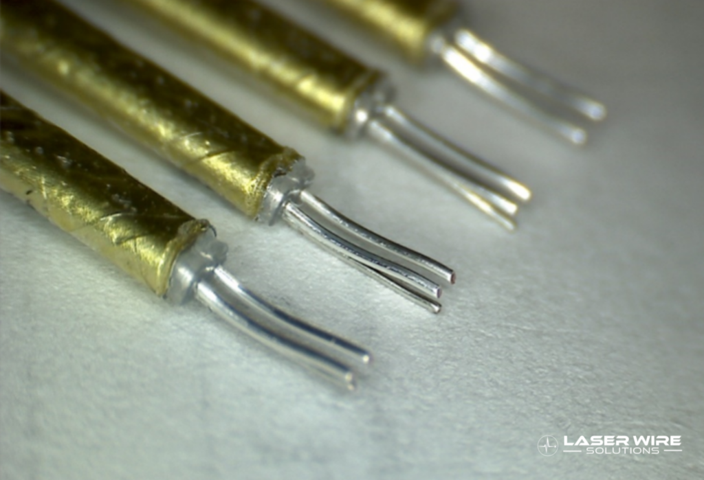
A twinax cable preparation specification should define the exposed conductor lengths, shield setback, retained dielectric geometry, drain-wire condition and inspection requirements needed for the intended termination. It should also identify the electrical tests used to assess the completed assembly. A clean-looking strip is useful evidence, but it does not establish signal integrity on its own.
For cable assembly manufacturers, the practical challenge is translating a connector design into a preparation process that can be repeated across material lots, fixtures and production shifts. That work should begin before choosing a stripping machine or requesting a cycle-time quotation.
Why does the termination region need its own specification?
Twinax carries a differential signal through two conductors within a shielded construction. At the connector, that controlled cable structure transitions into a different geometry. TE Connectivity identifies maintaining the appropriate impedance through the cable-to-connector termination as an important consideration in cabled backplane manufacturing.
The manufacturing implication is straightforward: the transition needs defined boundaries. Where does the shield end? How much dielectric remains? How are the conductors presented to the joining operation?
Treat these as engineering requirements rather than dimensions an operator adjusts until the assembly looks correct. The connector supplier’s current drawing and application instructions should establish the starting point; process development then determines how to achieve that geometry reliably.
Which dimensions should the strip drawing control?
Establish a common datum
Reference the preparation dimensions to a clearly identified feature, such as the cable end or a fixture-controlled stop. Explain whether each dimension is measured before or after slug removal and final trimming.
This avoids a basic but costly ambiguity: two teams can report the same strip length while measuring different physical features. Include a drawing or annotated photograph showing the measurement points.
Separate shield, dielectric and conductor requirements
Specify the jacket removal length, shield cut or setback position, retained dielectric length and exposed conductor length individually. Where the design includes a drain wire, define its required length and final position separately.
Avoid using one overall strip dimension as a substitute for this information. The same overall length can conceal different relationships between the shield edge, dielectric edge and conductor tips.
Define the allowable condition, not only the length
Include requirements for conductor straightness, strand condition where applicable, shield remnants, dielectric damage and loose metallic fragments. State how the operator or inspector should distinguish acceptable process marks from rejectable damage.
Use product-specific limits approved by the design owner. There is no universal shield setback or exposed-conductor dimension that applies to every twinax and connector combination.
What information should accompany the cable sample?
Provide the exact cable part number and revision, connector details and available material information. Include conductor construction, plating, dielectric type, shield arrangement and any adhesive or bonding layers relevant to removal.
LWS’s existing twinax guidance describes construction-dependent processing and the need for application trials. For a new project, supplement that construction review with the intended production presentation: single cable, grouped pairs or a fixture-loaded assembly.
A useful trial package also includes expected batch sizes, annual demand, upstream cut-length control, downstream joining method and the acceptable handling sequence. These details help prevent an attractive sample result from becoming an impractical production route.
How should laser trials be evaluated?
Start with the required output and assess each preparation stage against it. Record the sample identity, recipe revision, fixture arrangement and inspection results so the trial can be reproduced.
Evaluate the finished preparation after all required removal and handling steps. If a laser scribes a shield and a later operation peels it away, inspection should assess the condition after peeling, not only the initial scribe.
An illustrative trial matrix might vary an agreed laser parameter range alongside cable presentation and material lot. The purpose is to find a usable operating range and understand failure modes, rather than select the most visually attractive specimen.
Do not treat the absence of blade contact as proof that the conductor or dielectric cannot be affected. Laser suitability depends on the material, energy delivery and process conditions. The acceptance plan must still verify the features that matter to the assembly.
Which inspections and electrical checks are useful?
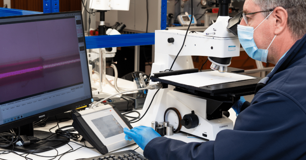
Use dimensional and microscopic inspection to assess the specified preparation features. Agree the magnification, lighting, measurement method and sampling approach before comparing trial results.
For electrical performance, involve the signal integrity team. Time-domain reflectometry can characterize impedance variations and locate discontinuities, but measurement quality depends on the stimulus, reference plane and test setup. Keysight explains these requirements in its TDR guidance.
Accordingly, compare assemblies using a controlled fixture and method. A changed cable-preparation process should not be judged from traces captured with inconsistent launches or reference planes. Depending on the design, the approved plan may also include continuity, isolation or frequency-domain measurements. Those tests and their limits belong to the product’s electrical requirements; they are not universal stripping-machine specifications.
How do you transfer the result into production?
Create a controlled preparation package containing the drawing revision, approved recipe, fixture identification, loading instructions and inspection criteria. Include photographs of acceptable and rejected conditions where they improve consistency.
Specify what happens after a failed first-piece check, a material substitution or a fixture change. Identify which changes require engineering review before production resumes.
Measure usable output through the complete sequence, including loading, removal, inspection and recovery from faults. A fast laser cycle does not establish assembly throughput if the next step becomes a handling bottleneck.
Frequently asked questions
What is the correct shield setback for twinax?
Use the connector and assembly design requirements. Shield setback depends on the particular termination; it should not be chosen from a generic value or copied from a different cable construction.
Is visual inspection enough to approve twinax preparation?
Visual and dimensional inspection can verify specified physical features. Where electrical performance is critical, the approved assembly test plan should also assess the relevant electrical characteristics.
Does laser stripping guarantee signal integrity?
No. It is one manufacturing step within a complete interconnect. Preparation quality, termination geometry, joining and the assembly design all need appropriate verification.
Discuss your twinax preparation requirements
Send Laser Wire Solutions your cable sample, connector drawing, required strip geometry and production targets. Our team can review the application and develop a processing approach for evaluation against your acceptance criteria.